On Splint Creation
After the scan data has been assigned, two key aspects of splint creation are confirmed with the user.
First, the target arch and splint type are defined. Three splint types are available, and depending on the selected type, specific modifications are applied to the splint outline and outer surface.
Splint Type | Description |
|---|---|
Michigan | A full-coverage splint for all general cases. |
Flat Plane | A full-coverage splint with a flat, smooth outer surface that enables unhindered mandible movement. |
Anterior Bite | A splint that covers only a portion of the front teeth and prevents contact between the back and canine teeth. |
Second, the design method is selected—either automatic or manual. The subsequent workflow varies depending on the selected method.
Auto Creation
Auto Creation is an automated splint design process that uses preset parameters. The workflow consists of three steps: Overview Mode → Design Mode → Labeling Mode.
Note
Learn more about modes later in this chapter.
Upon first selecting Auto Creation after installation, the default parameters are used to automatically create a splint. The default preset parameters are as follows:
Mode | Parameter | Default Value |
|---|---|---|
Occlusal Adjustment Mode | Distance to Antagonist | 1.5 mm |
Inner Surface Creation Mode | Inner Surface Offset | 0.10 mm |
Smooth Surface | 4/5 | |
Angle | 0.1° | |
Retention | 0 mm | |
Outline Designation Mode | Buccal Side | half the teeth height |
Lingual Side | half the teeth height | |
Outer Surface Creation Mode | Lingual & Buccal Thickness | 1.50 mm |
Smooth Surface | 5/5 | |
Dual Layer Splint | Off |
After the initial use, the most recently applied parameters are automatically saved and used for subsequent Auto Creation processes.
The parameters can be reviewed and modified by selecting “Parameter Settings” before creating the splint.
The next time Medit Splints is launched after using Auto Creation, feedback on the most recently auto-created splint will be requested. Based on the user’s response, the application will learn and automatically adjust the parameters to improve the fit of future splint designs. Providing feedback is optional.
Manual Creation
Manual Creation is a step-by-step splint creation process that provides greater flexibility for making fine adjustments to the splint. The workflow for Manual Creation is as follows:
Overview Mode → Edit Mode → Alignment Mode* → Occlusal Adjustment Mode* → Inner Surface Creation Mode* → Outline Designation Mode* → Outer Surface Creation Mode* → Design Mode → Labeling Mode |
|---|
Modes marked with an asterisk (*) include automatic analysis of the anterior and posterior teeth. Based on this analysis, suggested results are generated when the step is entered. The suggested results can be reviewed and modified if necessary before proceeding by clicking “Next.”
Modes
The complete workflow consists of 8 modes, each representing a specific step in the design process. These steps must be completed in the sequence in which they appear at the top.
If the occlusion was scanned in an open state or if only one arch is present, the Occlusal Adjustment Mode step may be skipped. After completion of the Design Mode step, the process may proceed directly to the final Complete step, and the results can be saved to Medit Link.
Overview Mode | Check your scan data | |
Edit Mode | Edit and trim data using the wide array of functions provided. | |
Alignment Mode | Align the data to the occlusal plane. | |
Occlusal Adjustment Mode | Adjust the occlusal relationship. | |
Inner Surface Creation Mode | Create the splint’s inner surface. | |
Outline Designation Mode | Designate the splint area. | |
Outer Surface Creation Mode | Create the splint’s outer surface. | |
Design Mode | Design the splint using the tools provided. | |
Labeling Mode | Label the splint by engraving or embossing the text. | |
Complete | Finish creating the splint and save the results to Medit Link. |
Note
The Edit Mode, Design Mode, and Labeling Mode are optional and can be skipped.
Overview Mode
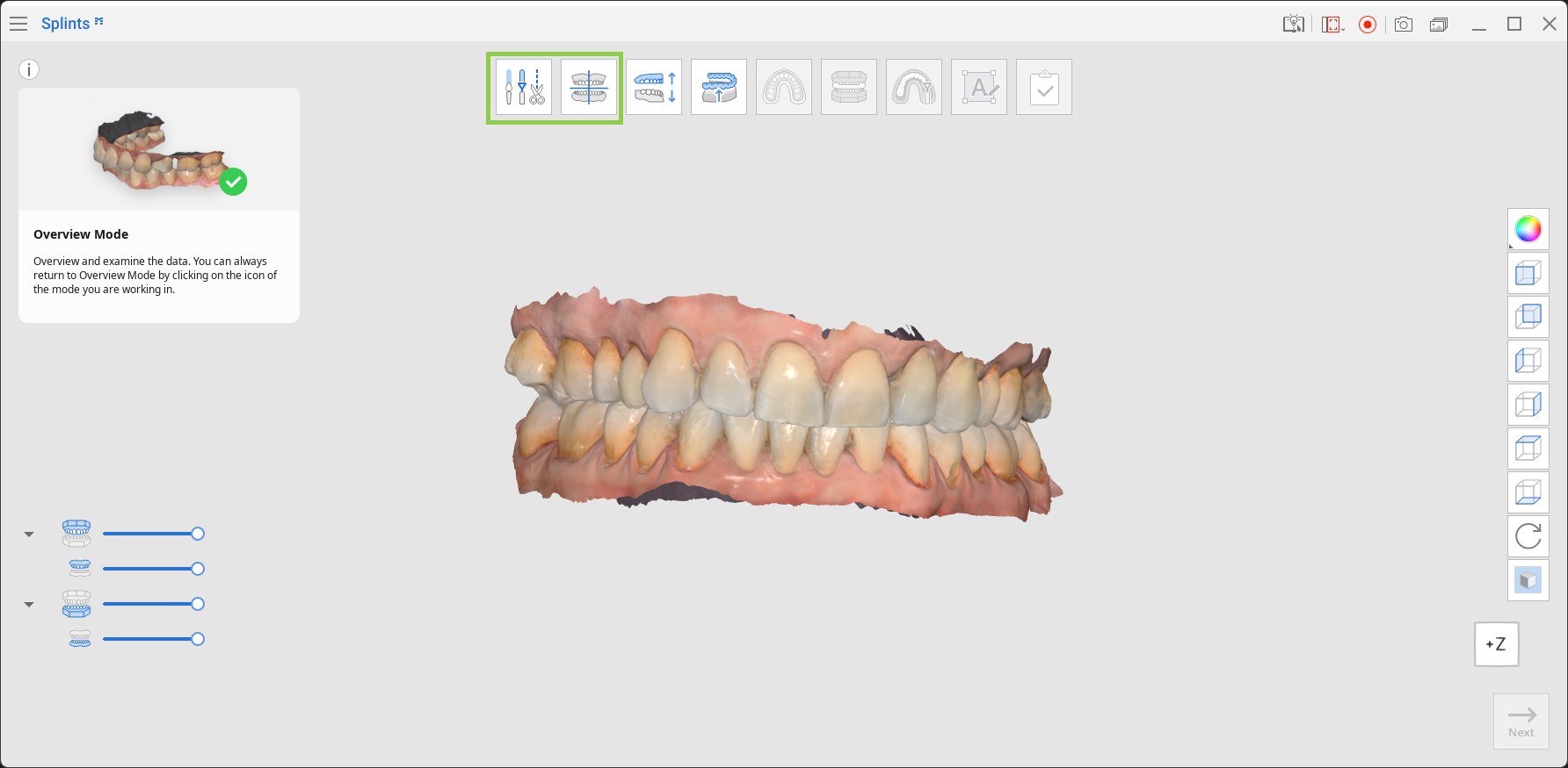
Overview Mode is the landing page of Medit Splints, where imported data is initially displayed.
Review the data, and if editing is required, click the Edit Mode icon at the top of the screen. If no editing is required, you may skip Edit Mode and proceed to Alignment Mode.
Edit Mode
Edit Mode allows users to modify the scan data before creating the splint. Unnecessary data can be trimmed, holes can be filled, and surfaces can be sculpted as needed.
Toolbox
Trimming Tool | Use various selection tools to remove unnecessary data. | |
Fill Holes | Fill empty spaces in the 3D mesh data. | |
Sculpting | Sculpt data by adding, removing, smoothing, or morphing. |
How to Trim Data
Use Smart Selection Tools to automatically select the teeth data, or choose “Polyline Selection” or “Brush Selection” to manually designate the trimming area.
To delete the selected area, click “Delete Selected Area.”
You can revert the selection by clicking “Invert Selected Area.”
You can switch the selection tool to deselection mode by clicking “Deselection Mode,” or use “Clear All Selection” to remove all selections.
Toolbox: Trimming Tool
Smart Teeth Selection | Automatically select all teeth of the arch, leaving out gingiva parts. | |
Smart Single Tooth Selection | Automatically select the area of a single tooth, leaving out gingiva parts. Click, press, and drag the mouse on the tooth. | |
Polyline Selection | Select all entities within a polyline shape drawn on the screen. | |
Brush Selection | Select all entities along a freehand-drawn path on the screen. The brush comes in three sizes. | |
Autofill Selected Area | Automatically fill in entities of the selected area. | |
Shrink Selected Area | Reduce the selected area each time you press the button. | |
Expand Selected Area | Expand the selected area each time you press the button. | |
Invert Selected Area | Invert the selection. | |
Deselection Mode | When on, this function deselects the area using various tools. | |
Clear All Selection | Clear all selected areas. | |
Delete Selected Area | Delete the data from the selected area. |
How to Fill Holes
Use “Fill Holes” to fill in any holes left from scanning or fill in deleted areas.
1. Maximum Perimeter of a Hole (mm)
Set the maximum hole size (in mm) to be filled. Holes larger than the specified size will not be filled.
2. Use Neighboring Colors for Filled Holes
When this option is enabled, the program uses surrounding colors to fill the holes. Otherwise, filled areas will appear gray.
3. Apply
Click the “Apply” button to apply the changes.
How to Sculpt Data
Select the “Sculpting” tool to modify the data. The sculpting tools allow you to add, remove, smooth, or morph parts of the data.
Toolbox: Sculpting
Add | Use the mouse to add data on the surface. | |
Remove | Use the mouse to remove parts of the data. | |
Smooth | Use the mouse to smooth parts of the data. | |
Morph | Use the mouse to morph parts of the data. |
Tip
To make sculpting easier, use shortcuts.
Click “Next“ when done editing.
Alignment Mode
This step automatically aligns the data to the virtual occlusal plane.
Once complete, further manual adjustments can be made if required. It is recommended to always check the alignment at this step to ensure proper positioning of the data.
Note
If alignment has already been completed in Medit Scan for Clinics or Labs, this step can be skipped.
Toolbox
Align with Occlusal Plane by Three Points | Select three points on the maxilla and mandible to align with the occlusal plane. | |
Align with Occlusal Plane by Four Points | Select four points on the maxilla or mandible to align with the occlusal plane. This option is useful when anterior teeth are not present. | |
Delete Marker Point | Remove the points selected for alignment. | |
Detach Data | Separate the aligned data and return it to its original position. | |
Multi-View | When enabled, this function displays the data from four different angles. |
To manually realign the data to the occlusal plane, follow these steps:
1. After automatic alignment is complete, click “Detach Data.”
2. Place three or four points on the data to align it to the occlusal plane.
3. Use Multi-View on the right to adjust the data and control the alignment process.
Note
When Multi-View is turned off, only the occlusal plane is displayed.
4. Click “Next” when finished.
Occlusal Adjustment Mode
In this step, space for the splint is created by adjusting the occlusal relationship between the maxilla and mandible.
Note
If the occlusion was scanned in an open state or only one arch is available, the Occlusal Adjustment Mode can be skipped.
1. To adjust the occlusal relationship, move the slider or enter a specific value for “Distance to Antagonist” or “Bite Opening.” Note that the bite opening value is automatically calculated based on the distance to the antagonist and may be automatically adjusted.
Toolbox
Bite Opening | Sets the degree of bite opening in the virtual articulator. | |
Distance to Antagonist | Sets the minimum distance between the occlusal surfaces of the maxilla and mandible. |
⚠︎ Caution
The distance to the antagonist must be greater than 0.0.
If it is set to 0.0, no space is created for the splint, and it is not possible to proceed to the next step. Adjust this value to ensure sufficient occlusal thickness for the splint.
2. Click “Next“ when finished.
Inner Surface Creation Mode
In this step, the inner surface of the splint is created by adjusting the inner surface offset, blockout direction, and blockout amount. The fit of the splint can be further refined using the “Retention” slider.
Toolbox
Inner Surface Offset | Sets the offset distance from the scan data to generate the splint mesh. | |
Smooth Surface | Smooths the inner surface of the splint. Move the slider to the right to increase smoothness. | |
Angle | Sets the blockout angle. | |
Retention | Controls the inclusion of undercut areas to improve splint retention. | |
Set Arrow to Viewpoint | Aligns the blockout direction arrow to face the current view. | |
Preview | Displays the blockout undercut areas on the data. |
1. Click and hold the arrow to move it freely and set the blockout direction. Areas included in the blockout are displayed in blue.
2. Set the inner surface offset, surface smoothness, and the blockout angle to adjust the splint’s tightness.
3. Use the “Retention” slider to adjust the range of allowed undercut areas and improve retention of the printed splint.
4. Click “Preview” to view the splint with blockout undercut areas.
5. Click “Next” when finished.
Outline Designation Mode
In this step, the outline of the splint is created on the buccal and lingual sides.
Toolbox
Buccal Side | Adjust the outline on the buccal side. Move the slider to the right to bring the outline closer to the gingiva. | |
Lingual Side | Adjust the outline on the lingual side. Move the slider to the right to bring the outline closer to the gingiva. |
1. In Outline Designation Mode, an outline is automatically generated. To modify the outline, drag the green points using the mouse or adjust the “Buccal Side” and “Lingual Side” sliders.
Moving slider to the left | Moving slider to the right |
|---|---|
2. If any section of the outline appears in red, adjust the line until it turns green. You cannot move to the next step while red sections remain.
3. When the outline is correctly defined, the selected area is displayed in blue. Left-click on the outline to add green points, and right-click to remove them.
4. Click “Next” when finished.
Outer Surface Creation Mode
In this step, the outer surface of the splint can be adjusted using the available tools.
1. Move the “Lingual & Buccal Thickness” slider to the right to increase the splint thickness on the lingual and buccal surfaces simultaneously. The occlusal surface thickness is automatically determined based on the distance to the antagonists.
2. Use the “Smooth Surface” slider to reduce roughness on the outer surface of the splint.
3. You can create a dual-material splint if your printer uses MultiJet printing technology. To do this, turn on "Dual Layer Splint" at the bottom, and the splint will be divided into outer and inner layers.
Toolbox
Lingual & Buccal Thickness | Adjust the splint thickness on the lingual and buccal surfaces. | |
Smooth Surface | Smooth out the outer surface of the splint. | |
Dual Layer Splint | Split the splint mesh into outer and inner layers for dual-material printing. |
4. Click “Next” when finished.
Design Mode
In this mode, final design adjustments can be made to the splint. Use the available tools to analyze occlusal contact points, remove intersections with the antagonist, and verify the splint’s thickness.
Toolbox: Main
Color Map On/Off | Toggle the color map display. | |
Switch Deviation Display Area | Switch the deviation display between the full data and contact areas only. | |
Adapt to Antagonist | Adjust the splint to remove intersections with the antagonist. | |
Measurement Tools | Create section lines and measure distances between points. |
Toolbox: Sculpting
Add | Use the mouse to add data on the surface. | |
Remove | Use the mouse to remove parts of the data. | |
Smooth | Use the mouse to smooth parts of the data. | |
Morph | Use the mouse to morph parts of the data. |
Toolbox: Measurement Tools
Create Sections | Create section lines. | |
View Perpendicularly to Section Line | Align the view perpendicular to the selected section line. | |
Measure Distance by Two Points | Measure the distance between two points. | |
Measure Distance by Three Points | Measure the distance between a point and a line defined by two other points. | |
Delete Measurement Results | Delete measurement results and section lines. |
1. Use the Sculpting tools to add, remove, smooth, or morph the outer surface of the splint. This can help you make finer adjustments to the splint’s design.
2. Enable the Color Map to identify intersections. Red areas indicate intersections between the splint and opposing data.
3. Click “Switch Deviation Display Area” to evaluate the distance to the antagonist.
4. Click “Adapt to Antagonist” to remove all intersections between the splint and the antagonist.
5. Use “Measurement Tools” to verify the splint thickness after editing. Create section lines and measure distances by selecting points on the data.
6. Click “Next” when finished designing the splint.
Labeling Mode
Labeling Mode provides tools for creating and managing labels on the splint surface. A default label (Label #1) is automatically created on the outer surface of the splint.
Note
Adding labels is optional.
Toolbox
Add Label | Add a new label to the splint. | |
Manage Label #1 | Edit, emboss, or engrave label #1. | |
Manage Label #2 | Edit, emboss or engrave label #2. | |
Label | Enter the text to appear as a label. | |
Font | Choose a font for the label. | |
Size | Set the label size. | |
Engraving | Label the splint by engraving. | |
Embossing | Label the splint by embossing. | |
Rotate 180° | Turn the selected label by 180°. | |
Delete | Delete the current label. |
1. Check the placement of the automatically created label. If any part of the label appears in orange, drag it until it is fully displayed in blue.
2. Click “Embossing/Engraving” to change the marking method. The labeling depth can be adjusted as needed.
3. To add additional labels, click “Add Label.” Up to six labels can be created.
You can rotate a label by clicking it and using “Rotate 180°.”
4. To delete a label, select the icon with the target label’s number and click “Delete.”
5. Select each label to adjust its font and size.
6. Click “Next” when finished.
Complete
Once the splint creation process is complete, click the final icon at the top of the screen to save the results to the Medit Link case. Enter a project file name and click “Save.”
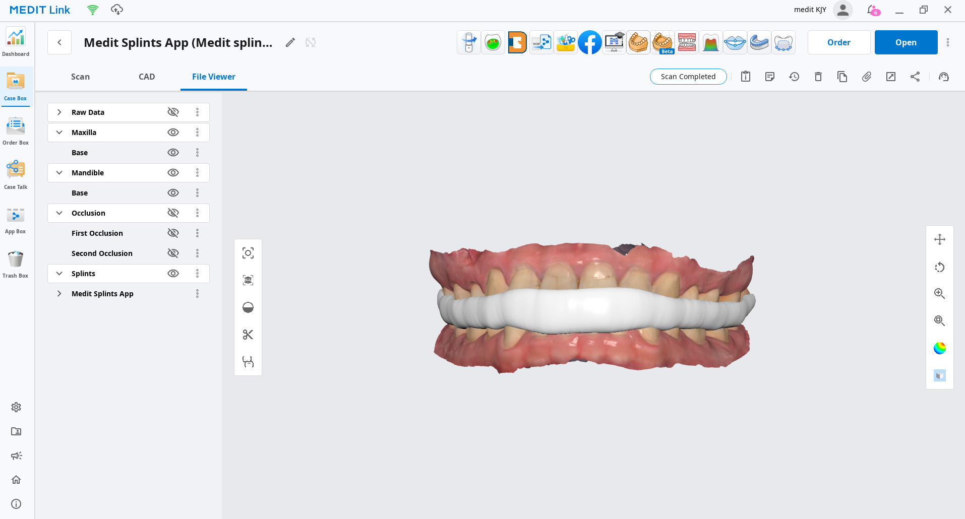
The saved data (both the project file and the final splint design) can be checked in the Medit Link case.
Comments
0 comments
Please sign in to leave a comment.